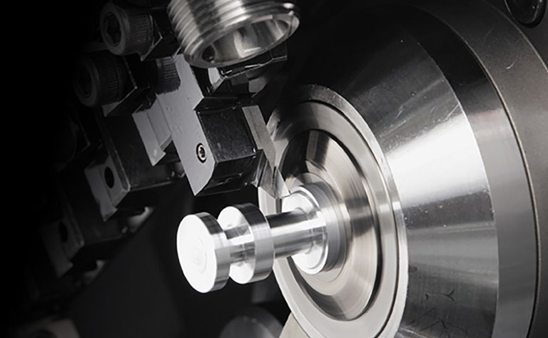
Pure Copper Processing SolutionsFor turning small parts | UC1 and Y axis holder + High-pressure coolant
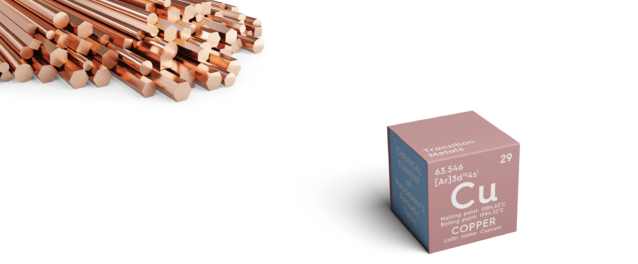
The Master of Pure Copper Processing
The search for an answer led me to NTK
NTK's Work Changing Concept
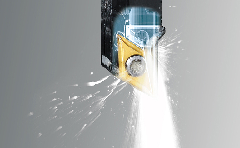
Diamond-coated carbide : Longer tool life with UC1
Improved chip control with Y-axis tool holder + high-pressure coolant
Performance
- High purity, high hardness diamond coating, and excellent adhesion performance enable long-term stable machining
- Improved chip control by applying Y-axis direction machining with high-pressure coolant
Applications
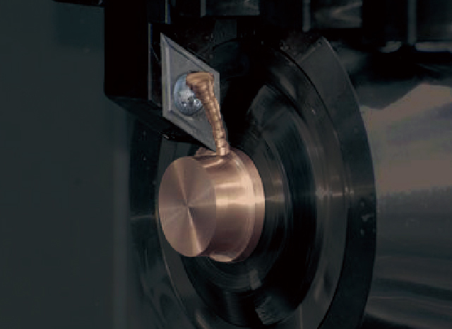
Pure copper (C1020/C1100) machined using Sliding head automatic lathes or CNC-lathes
Diamond-coated carbide:UC1
〔 Machining Property of C1100 Tough Pitch Copper 〕
Diamond-coated carbide: UC1 with excellent wear resistance & welding resistance is recommended because tooling tends to wear and the machined surface deteriorates due to welding, resulting in short tool life.
A good machined surface can be obtained by applying the appropriate cutting condition (low cutting depth/low feed) which reduces the chip thickness.
Case Study
| Battery connector | |
|---|---|
|
C1100 φ.394 -.787 in. |
|
180 - 360 |
|
.0012 |
|
.008 |
|
WET |
| UC1 DCMT32.508 FNAM3 | 1000 pcs / corner |
| PVD super coat DCGT32.508 molded chipbreaker |
50 pcs / corner |
| Electrode part | |
|---|---|
|
C1100 φ.472 in. |
|
262 |
|
.002 |
|
.040 |
|
WET |
| UC1 DCMT32.504 FNAM3 | 2000 pcs / corner |
| PVD super coat DCGT32.504 molded chipbreaker |
100 pcs / corner |
Machined Surface Comparison
- [ Cutting conditions ]
- Part material : C1100 vc=260 SFM ap=.040 WET
- [ Tools used ]
- DCMT32.508FNAM3 UC1
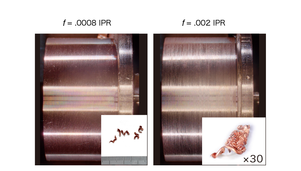
If the cutting conditions cause the chips to become thick (high cutting depth or high feed) then the machined surface will deteriorate due to chip clogging.
Cutting conditions
Scroll the table →
| Grade | Tool | Operation | Machining | Speed (SFM) | Feed (IPR) | DOC (inch) | WET |
|---|---|---|---|---|---|---|---|
| UC1 | Tough pitch copper C1100 | Turning | Rough - Finish | 160 - 500 | .0008 - .002 | .008 - .080 | ● |
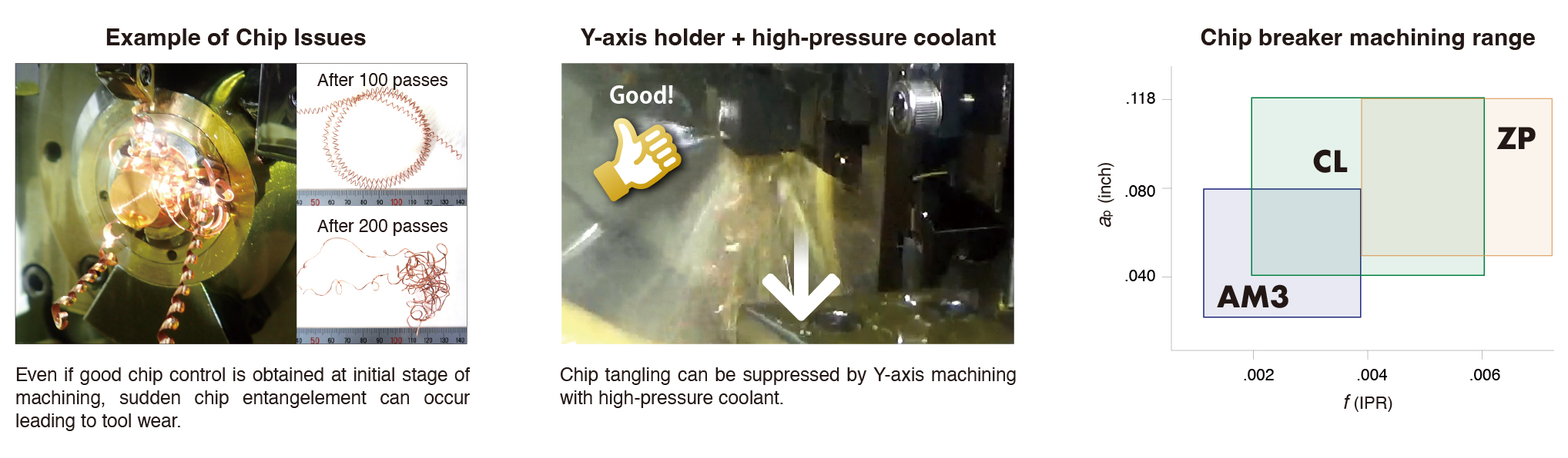
Using the cutting conditions shown, chips can be segmented and controlled with AM3 chipbreaker.
When machining at large depths of cut and high feed rate, select CL or ZP chipbreakers to suppress chip clogging.
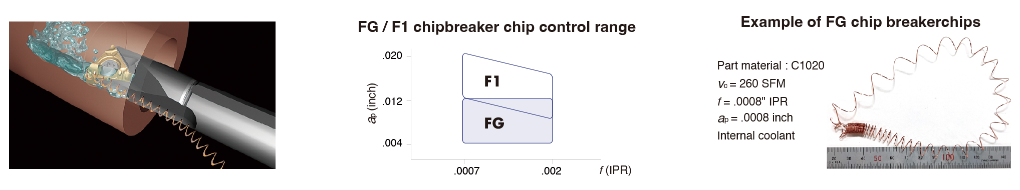
〔 Machining Properties of C1020 Oxygen-free Copper 〕
Stable chip generation may be difficult with a chip breaker alone, it is recommended to add a Y-axis holder + high pressure coolant
Scroll the table →
Cutting Conditions
Scroll the table →
| Grade | Tool | Operation | Machining | Speed (SFM) | Feed (IPR) | DOC (inch) | WET |
|---|---|---|---|---|---|---|---|
| UC1 TM4 | Oxygen-free copper C1020 | Turning | Rough - Finish | 160 - 500 | .0008 - .008 | .020 - .118 | ● |
Refer to content above to select cutting conditions and chip breaker to obtain good chip control.
If you want longer tool life than PVD Carbide: TM4, use Diamond-Coated Carbide: UC1.
〔 Boring 〕
Improve chip control by using FG/F1 chip breakers to evacuates chips backwards and high-pressure coolant
Scroll the table →
Cutting conditions
Scroll the table →
| Grade | Tool | Operation | Machining | Speed (SFM) | Feed (IPR) | DOC (inch) | WET |
|---|---|---|---|---|---|---|---|
| UC1 TM4 | C1100 C1020 | Turning | Finish | 160 - 500 | .0008 - .002 | .004 - .020 | ● |
If you want longer tool life than PVD Carbide: TM4, use Diamond-Coated Carbide: UC1.
Insert lineup
Scroll the table →
| ●: Stock ○: 1-2 week delivery |
||||||||||
| Shape | EDP | Item Number | Corner R | Grade | Dimensions (inch) | |||||
|---|---|---|---|---|---|---|---|---|---|---|
| UC1 | TM4 | IC | Thickness | |||||||
| AM3 | 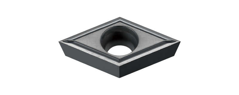 2 corners available 2 corners available |
5970728 | DCMT | 32.504 FN | AM3 | .004 | ● | 3/8 | 5/32 | |
| 5970736 | 32.508 FN | AM3 | .008 | ● | ||||||
| 5970744 | 32.51 FNA | AM3 | .016 | ● | ||||||
| F1 ※ | 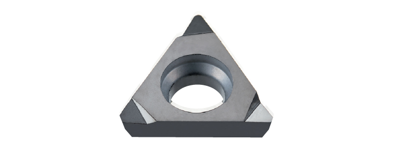 3 corners available 3 corners available |
5970702 | TPMH | 2208 FR | F1 | .008 | ○ | 1/4 | 1/8 | |
| 5970710 | 221 FR | F1 | .016 | ○ | ||||||
| ZP | 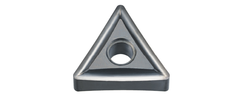 6 corners available 6 corners available |
5970686 | TNMG | 3308 FN | ZP | .008 | ● | 3/8 | 3/16 | |
| 5967351 | 331 FN | ZP | .016 | ● | ||||||
| 5970694 | 332 FN | ZP | .031 | ● | ||||||
| ZP | 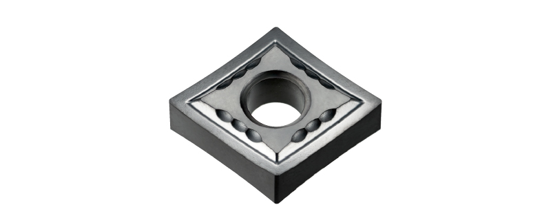 4 corners available 4 corners available |
5970660 | CNMG | 431 FN | ZP | .015 | ● | 1/2 | 3/16 | |
| 5970678 | 432 FN | ZP | .031 | ● | ||||||
| AM3 | 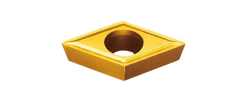 |
5694633 | DCGT | 32.504M FN | AM3 | .003 | ○ | 3/8 | 5/32 | |
| 5694641 | 32.508M FN | AM3 | .007 | ○ | ||||||
| 5693783 | 32.51M FN | AM3 | .015 | ○ | ||||||
| CL※2 | 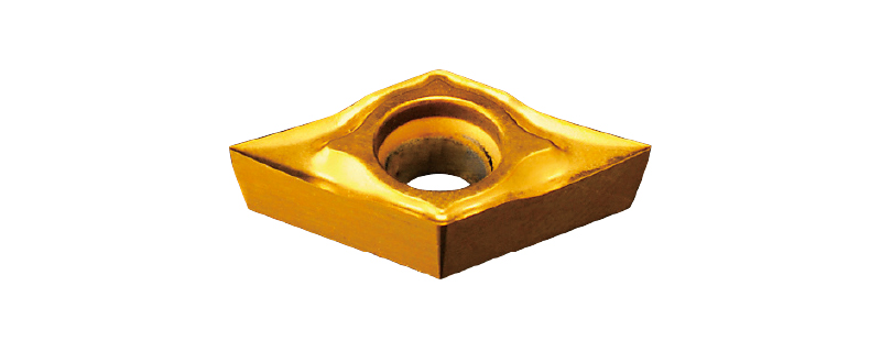 |
5757091 | DCGT | 32.504M | CL | .003 | ● | 3/8 | 5/32 | |
| 5758040 | 32.508M | CL | .007 | ● | ||||||
| 5765730 | 32.51M | CL | .015 | ● | ||||||
| FG※ | 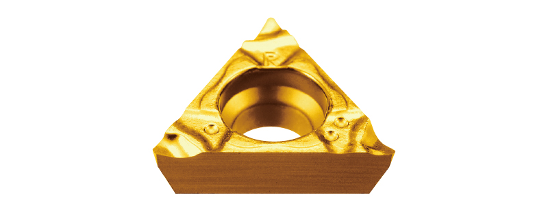 R-hand shown R-hand shown |
5790100 | TPGP | 7308 R | FG | .008 | ● | 7/32 | 3/32 | |
| 5790092 | 731 R | FG | .016 | ● | ||||||
| 5790142 | TPGH | 2208 R | FG | .008 | ● | 1/4 | 1/8 | |||
| 5790134 | 221 R | FG | .016 | ● | ||||||
| ZP | 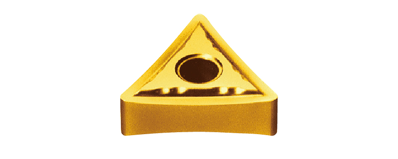 |
5731146 | TNGG | 3308 FN | ZP | .008 | ○ | 3/8 | 3/16 | |
| 5731211 | 331 FN | ZP | .016 | ○ | ||||||
* The R symbol (01M,02M,04M,08M) can be used for machining where the R indication of the workpiece part is less than or equal to R0.1,R0.2,R0.4,R0.8.
* Right-hand inserts with FG and F1 chipbreakers should be used with right-hand holders
*2 The CL breaker differs slightly from the above dimensions due to product specifications, but there is no problem with machining.
Other recommended products
-
Solution for Machining PlasticsFor turning small parts | Y-axis holder + KM1 Insert
New Chip Control Proposal for Plastics
-

Y-axis holder seriesSelection for Front turning, back turning, grooving, Multi-functional groover (application-spool parts) | For Swiss CNC lathes (vertical gang style)
Uses gravity to direct chips downward away from part
-
GTPAMultifuntioning tool for machining non-ferrous material| Swiss CNC Lathes
Best tool for machining aluminum valve spool parts
-
SPLASH seriesCoolant through toolholders | Swiss CNC Lathes
Extensive selection of styles and sizes
Useful information
 4 STEP-NTK Cutting Tools Lab for choosing suitable cutting tool for cut-off machining
 The aspects of "chip control" that you should check when workpiece damage or poor dimensioning are detected during Swiss type CNC automatic lathe machining
 Two Areas to Check When Coaxiality is Not Achieved During Swiss CNC Lathe Machining
 "Two" checkpoints and measures to be checked when "Roundness" does not come out in Swiss-type CNC-automatic lathe machining-NTK Cutting Tools Lab