
Solution for Machining PlasticsFor turning small parts | Y-axis holder + KM1 Insert
New Chip Control Proposal for Plastics
The Realization of Stable Machining
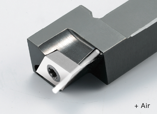
Improved chip control with a Y-axis holder
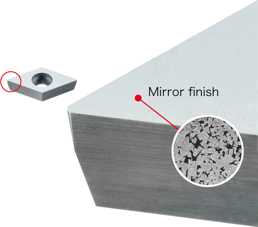
High quality surface finish with KM1
Performance
- Applying Y-axis machining eliminates chip control issues
- Mirror-finish polished fine grain cemented carbide ensures an excellent surface finish
Tooling application
Automatic lathe (Gang type) machining plastic materials (PEEK/PTFE, etc.)
Front turning (ISO) / Back turning / Grooving / Cut-off / Threading / Boring
Y-axis + Air
Cutting conditions
Scroll the table →
| Grade | Material | Operation | Machining | Cutting speed (SFM) | Feed (IPR) | DOC (inch) | DRY | AIR |
|---|---|---|---|---|---|---|---|---|
| KM1 | Plastic (PEEK,PTFE,etc.) | Turning | Roughing - Finishing | 164 - 490 | .002 -.004 | .020 - .118 | ● | ● |
Chip Control Performance
Scroll the table →
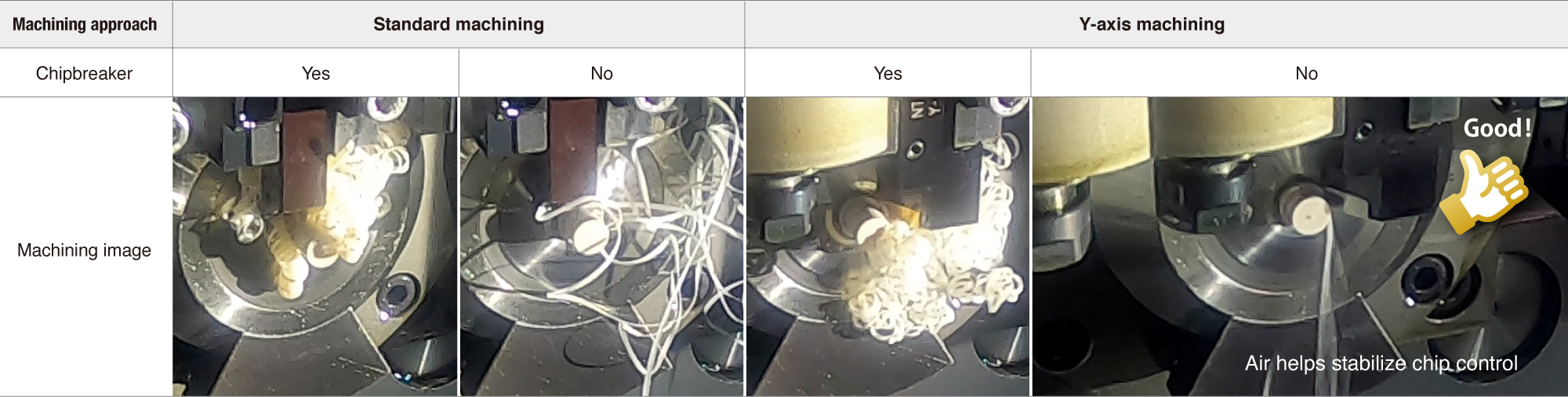
- [ Cutting condition ]
- Material : PEEK(φ10) 267 SFM .002 IPR .039 DOC
Machining Performance of NTK Carbide
Excellent surface finish using an insert featuring an up-sharp edge and polished mirror-finish for welding resistance.
Case study
| Medical implant | |
|---|---|
|
PEEK |
|
328 |
|
.0023 |
|
.010 |
|
NTK:AIR Competitor:DRY |
| KM1 VCGT11T302H No chipbreaker | 80 pcs / corner |
| Carbide VCGT11T302 Molded chipbreaker | 40 pcs / corner |
| Automotive component | |
|---|---|
|
PEEK (with glass fiber) |
|
NTK:394 Competitor:131 |
|
NTK:.003 Competitor:.002 |
|
.010 |
|
NTK:AIR Competitor:DRY |
| KM1 DCGT11T302H No chipbreaker | 3 pcs / corner |
| PVD Carbide VNMG160408 Molded chipbreaker | 1 pcs / corner |
Lineup
| Standard holder | □ 3/8 , 1/2 , 5/8 , 3/4 * Coolant through available from □3/8 |
| Y-axis coolant through holder | □ 3/8 , 1/2 , 5/8 |
| Boring bar | Minimum machining diameter: Standard holder - from φ.039″ * Coolant through holder - from φ.0866″ available |
* For details, please refer to the NTK General Catalog or Swiss Tooling Catalog.
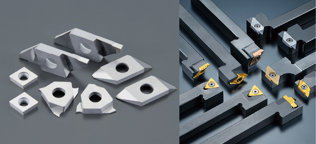
Insert Lineup
Scroll the table →
| Shape | EDP | Item number | Corner R | Grade | Dimensions (mm) | Remarks | |||
|---|---|---|---|---|---|---|---|---|---|
| KM1 | IC | Thickness | |||||||
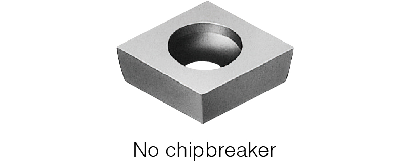 |
5556196 | CCGW | 21.501 | H | .001 | ● | 1/4 | 3/32 | |
| 5556204 | 21.504 | H | .004 | ● | |||||
| 5556212 | 21.508 | H | .008 | ● | |||||
| 5556220 | 32.501 | H | .001 | ● | 3/8 | 5/32 | |||
| 5556246 | 32.504 | H | .004 | ● | |||||
| 5556253 | 32.508 | H | .008 | ● | |||||
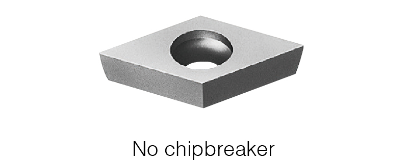 |
5556139 | DCGW | 21.501 | H | .001 | ● | 1/4 | 3/32 | |
| 5556147 | 21.504 | H | .004 | ● | |||||
| 5556154 | 21.508 | H | .008 | ● | |||||
| 5556162 | 32.501 | H | .001 | ● | 3/8 | 5/32 | |||
| 5556170 | 32.504 | H | .004 | ● | |||||
| 5556188 | 32.508 | H | .008 | ● | |||||
| 5556295 | DCGW | 21.502 | RH-WP | .002 | ● | 1/4 | 3/32 | with wiper | |
| 5556303 | 32.502 | RH-WP | .006 | ● | 3/8 | 5/32 | |||
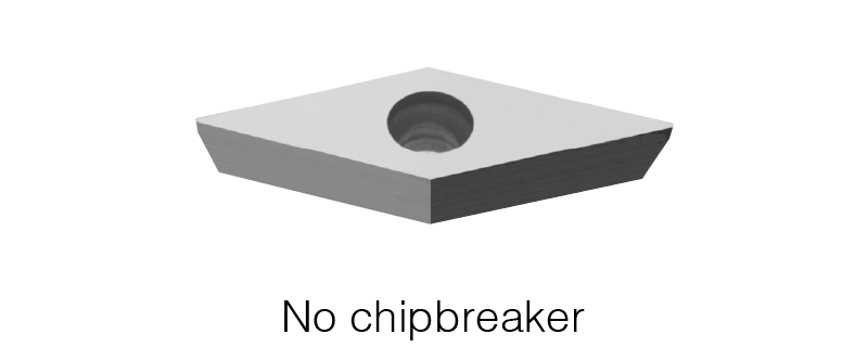 |
5556261 | VCGW | 2201 | H | .001 | ● | 1/4 | 1/8 | |
| 5556279 | 2204 | H | .004 | ● | |||||
| 5556287 | 2208 | H | .008 | ● | |||||
Features of TFD type
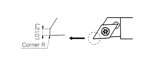
* The insert geometry of the TFD-style is the same as a DCGT style.
* The TFD style insert is designed with a 0.012 inchwiper flat when the insert is set in the holder; enabling improved work surface finish at increased feed rates.
* The TFD-style inserts can be used on toolholders (SDJC-N, SDJC-N-F, SDJC, CH-SDUC, Y-SDJC, Y-SDJC-OH) with a cutting edge angle of 93°.
Other recommended products
-
Pure Copper Processing SolutionsFor turning small parts | UC1 and Y axis holder + High-pressure coolant
The Master of Pure Copper Processing The search for an answer led me to NTK
-

Y-axis holder seriesSelection for Front turning, back turning, grooving, Multi-functional groover (application-spool parts) | For Swiss CNC lathes (vertical gang style)
Uses gravity to direct chips downward away from part
-
GTPAMultifuntioning tool for machining non-ferrous material| Swiss CNC Lathes
Best tool for machining aluminum valve spool parts
-
SPLASH seriesCoolant through toolholders | Swiss CNC Lathes
Extensive selection of styles and sizes
Useful information
 4 STEP-NTK Cutting Tools Lab for choosing suitable cutting tool for cut-off machining
 The aspects of "chip control" that you should check when workpiece damage or poor dimensioning are detected during Swiss type CNC automatic lathe machining
 Two Areas to Check When Coaxiality is Not Achieved During Swiss CNC Lathe Machining
 "Two" checkpoints and measures to be checked when "Roundness" does not come out in Swiss-type CNC-automatic lathe machining-NTK Cutting Tools Lab