
Ceramic inserts are tool materials that can greatly increase the processing efficiency of heat-resistant alloys.
However, there are a lot of ceramics, and it is difficult to determine which material is good and how to use it.
In this column, we will introduce the selection and utilization points for achieving more stable process by maximizing the performance of ceramics in milling rough to semi-finished machining of heat-resistant alloys.
Point 1. Choose the best ceramic insert material for milling
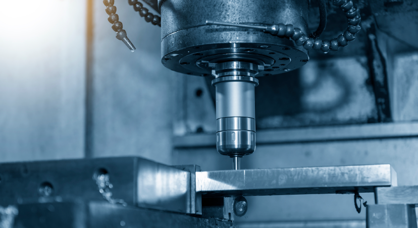
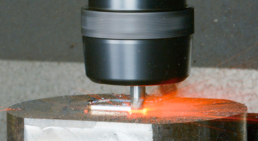
Unlike turning, milling is performed by rotating the cutting tool itself and moving the workpiece.
Since the insert cutting edges cut into the workpiece one after another, the process is always in the “intermittent machining” state.
Therefore, chipping of the cutting edge are likely to occur, and high strength is required for ceramic inserts.
As a ceramic material for milling heat-resistant alloys, NTK recommends SiAlON-based ceramics with superior impact resistance.
Since there are several types of SiAlON ceramic materials, the characteristics of each material are listed in the table below.
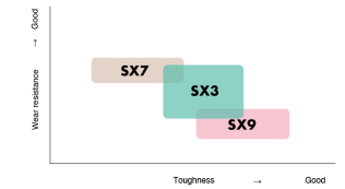
Depending on the material, the product lineup emphasizes wear resistance, chipping resistance, and balance.
When selecting the material, the optimum material varies depending on the condition of the workpiece to be machined.
When milling heat-resistant alloys, it is recommended to select tools according to the following procedure.
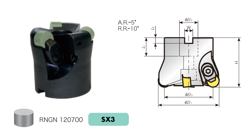
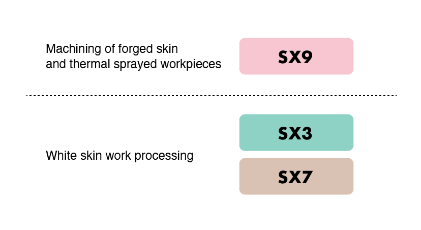
1st recommendation: Select insert geometry “RNGN” type, material “SX3”
If machining is not restricted, we recommend using the insert-shaped “RNGN” type with the highest cutting edge strength, and the sialon-based ceramic material “SX3” with excellent wear resistance and chipping resistance.
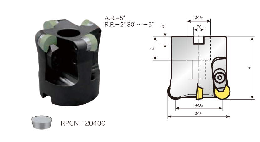
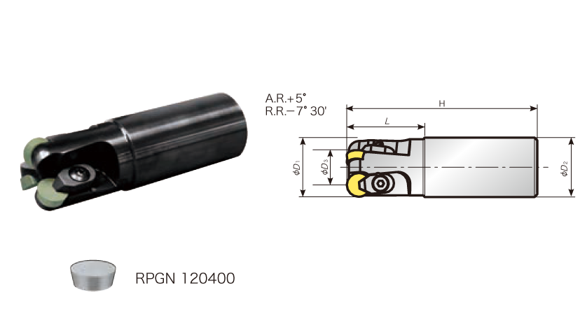
2nd recommendation: Select insert geometry “RPGN” types (When there are machining restrictions and insert-shaped “RNGN” types cannot be used)
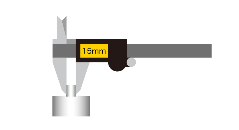
When the workpiece thickness is thin (approx. 15 mm or less) and workpiece clamping rigidity is insufficient, we recommend the use of insert shape “RPGN” type to reduce cutting resistance.
| Work clamp rigidity is weak.
|
| Thin workpiece
|
 |
 |
| The optimum insert material varies depending on the condition of the workpiece being machined.
Since machining of forged scale and thermal sprayed workpieces is highly intermittent, we recommend the use of “SX9” material, which has excellent chipping resistance. |
 |
Point 2: Milling method that takes advantage of machining heat
As described in the column “Tips for effectively cutting nickel-based alloys by knowing the material’s characteristics” heat-resistant alloys, which are difficult to machine due to their superior high-temperature strength, have a characteristic that their strength decreases at once after a certain temperature, making them easier to cut.
Taking advantage of the characteristics of ceramics with excellent heat resistance, it is possible to increase the temperature by increasing the cutting speed and to process the workpiece with high efficiency while softening it. Therefore, in milling of heat-resistant alloys, it is important to process without escaping the processing heat produced by high-speed processing.
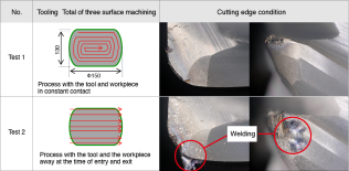
In order to investigate the effect of thermomechanical processing on ceramic tools, we carried out processing tests using two patterns of tooling as shown below.
In order to investigate the effect of thermomechanical processing on ceramic tools, we carried out processing tests using two patterns of tooling as shown below.
The Test1 is tooling in which machining is performed with the tool and the workpiece contacted at all times, and the Test2 is tooling in which the tool and the workpiece are separated at the time of entry and exit.
All other than the tooling, such as the ceramic tools and cutting conditions used, are the same conditions.
 |
 |
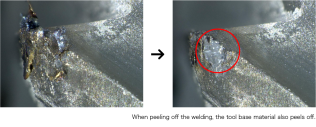
 ※ Do not remove the welded part attached to the cutting edge after machining.
When removing it, the base material of the insert may also peel off at the same time, making it impossible to continue using it.
TThe tooling of the Test1 ensures that the tool and the workpiece are as far away as possible. This enables machining while maintaining the softening action of the workpiece due to processing heat, thereby reducing tool damages.
The Test2 is cooled because the machining point moves away even when the machining temperature rises, resulting in heat cracks on the tool side, falling off of welding, and work-hardening on the workpiece side. As a result, tool damage easily progresses.
Point 3. Insert corner replacement procedure after machining
If the insert corner is replaced with welding on the cutting edge, a gap will be left at the insert mounting point.
If machining with a gap is done, the insert cannot be clamped firmly, which may result in chattering or defects. We will introduce the points to prevent such problems.
Key Points for Maximizing the Performance of Combined Ceramic Inserts 〔 Milling of Heat-Resistant Alloys 〕
- Insert geometry “RNGN” type, material “SX3” to be Selected.
- Tooling to be assembled taking advantage of machining heat.
- When replacing inserts, be careful of gaps in the mounting area (welding of the cutting edge)
For details on milling tools and tooling for heat-resistant alloy machining, please contact us.